Damage to the Flap drive torque tube in fuselage.
IN REFERENCE TO: Damage to the flap drive torque tube in the fuselage.
ISSUE DATE: January 18, 2017
EFFECTIVE DATE: Immediately, imperative before the next flight
RESTRICTIONS: Not applicable
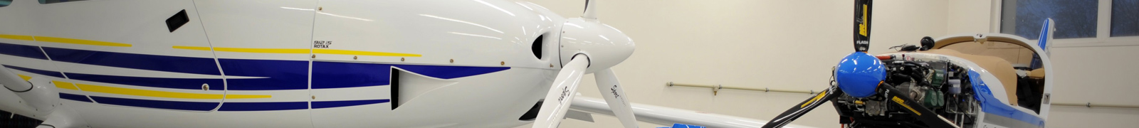
AFFECTED PRODUCTS: TL 3000 Sirius serial numbers
SERIAL NUMBERS OF THE AFFECTED AIRCRAFT: All serial numbers
BULLETIN NUMBER: 3.S.SI.2017
SUPERCEDED BULLETIN NUMBER (if applicable): N/A
NUMBER OF PAGES: 7
DISTRIBUTION: www.tl-ultralight.com manufacturer's website, Pilot magazine, LAA CR
REFERENCES: www.tl-ultralight.com
PRECAUTION:
During a planned service check on one of the TL 3000 Sirius aircraft, it was discovered that, due to a fault in a metal mounting bracket which supports the flap drive torque tube in the fuselage, excessive wear of the cross-tube surface has occurred. This might affect the material strength of this particular part. Reduction of the torque tube´s strength could lead to a serious fault in the flap control path. As this type of damage becomes apparent after long-term operation only, it is necessary to perform an immediate inspection of this mounting. The shape of the metal that holds the sliding mount ensures the axial position of the sliding bearing that is fitted over the torque tube. Excessive bending of the two metal safeguards can lead to contact between the locking part of the metal and the rotating torque tube (especially at high speed rotation of the torque tube). This, in combination with the tube´s rotation, creates a groove along the circumference of the tube that weakens its cross-section and load capacity. Immediate inspection of this aircraft section ensures early detection of any possible damage to the torque tube and allows for replacement of faulty and damaged parts. The objective of the above described solution is to eliminate any possibility of presence of faulty metal torque tube mounting and damage to the torque tube. In case of discovery of the above-mentioned damage, it is necessary to contact the aircraft manufacturer and to perform an urgent replacement of the damaged parts prior to the next flight. This Service Bulletin contains inspection instructions so that they can be performed correctly and independently by the aircraft operator. The new parts including the torque tube and metal mounting holder can be obtained via the TL-ULTRALIGHT manufacturer free of charge upon written request with stated delivery address and upon the payment of the transportation cost.
In the case of non-compliance with this Bulletin, the manufacturer reserves the right to refuse any possible damage claims resulting from not complying with this Bulletin.
Inspection procedures:
Sequence of steps, Description of Operation
Aircraft preparation
- Move the plane into a suitable work area and fix wheel chocks
- Make sure that all switches are off and the rescue system is secured
against activation.
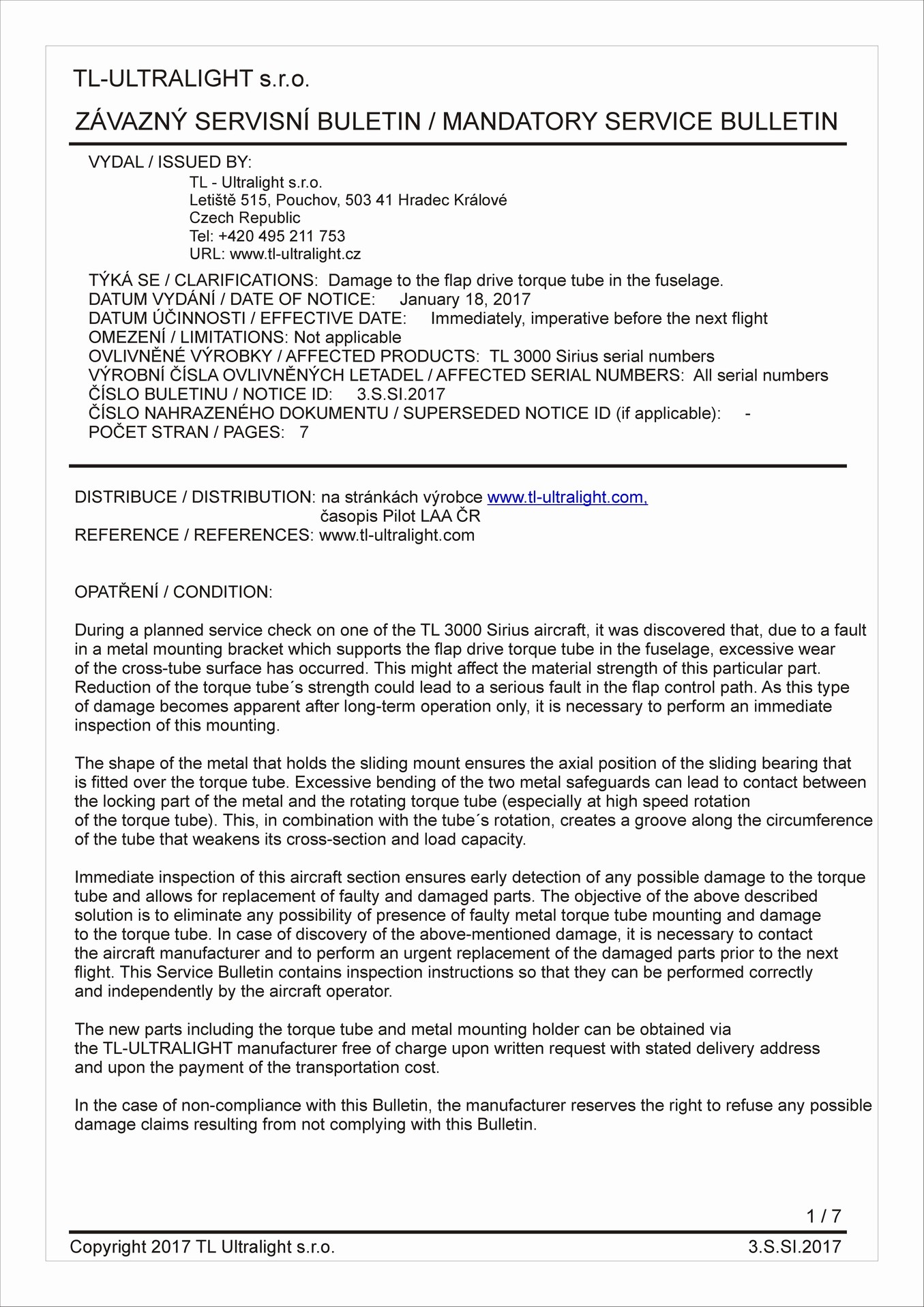
Dismantling of overhead instrument panel
- Remove the overhead instrument panel from the ceiling panel (if the aircraft has an overhead instrument panel). The instrument panel is secured to the composite roof panel with seven M4x12 screws (cross headed). The instrument panel will remain suspended from the ceiling of the aircraft on the cables from the instruments.
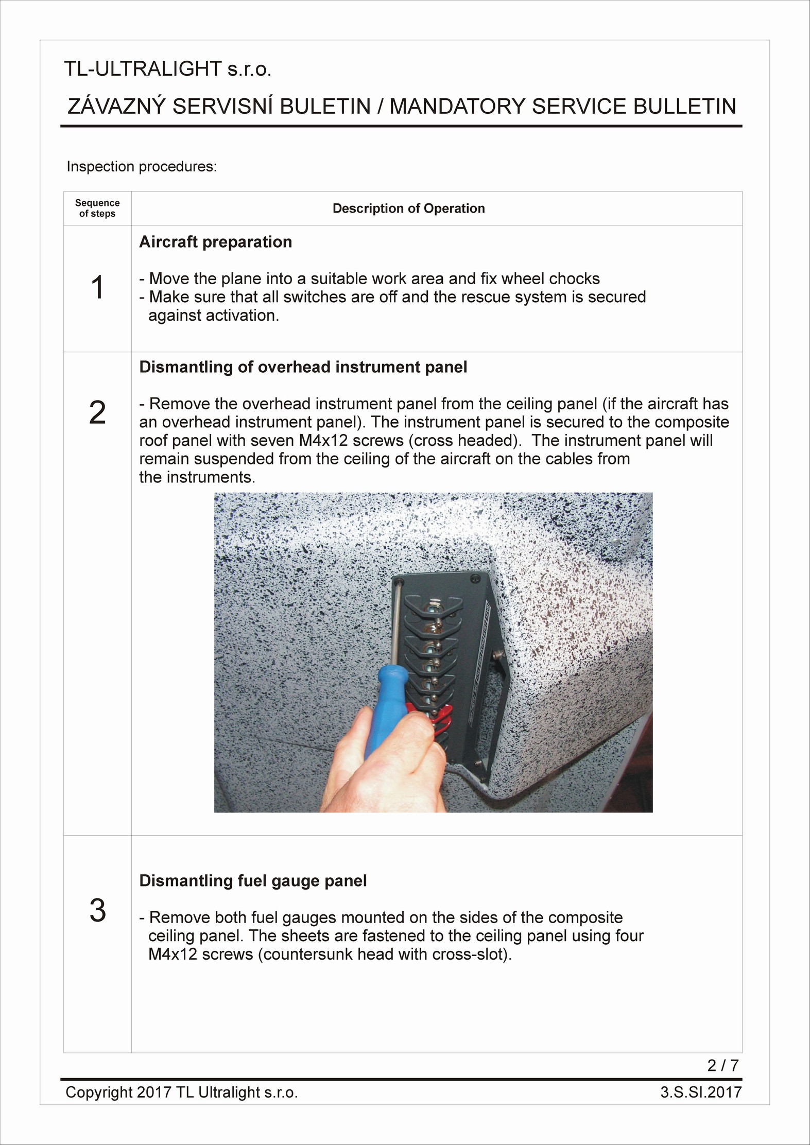
Dismantling fuel gauge panel
- Remove both fuel gauges mounted on the sides of the composite ceiling panel. The sheets are fastened to the ceiling panel using four M4x12 screws (countersunk head with cross-slot).
1 ....Composite ceiling panel
2 ... Transparent fuel gauge cylinder
3 ... Internal part of the fuel gauge
4 ... Outer metal part of the fuel gauge
5 ... M4x12 screw
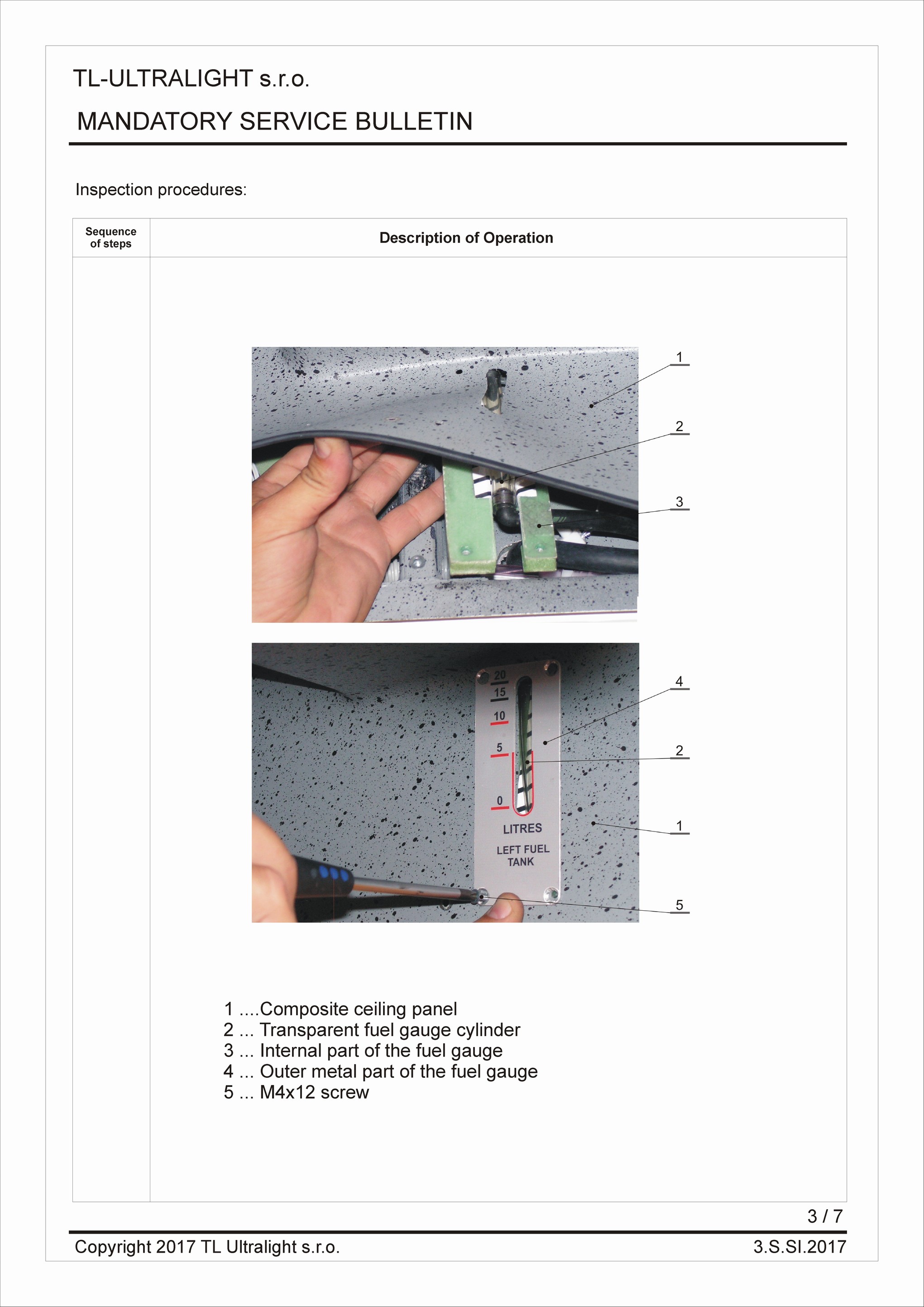
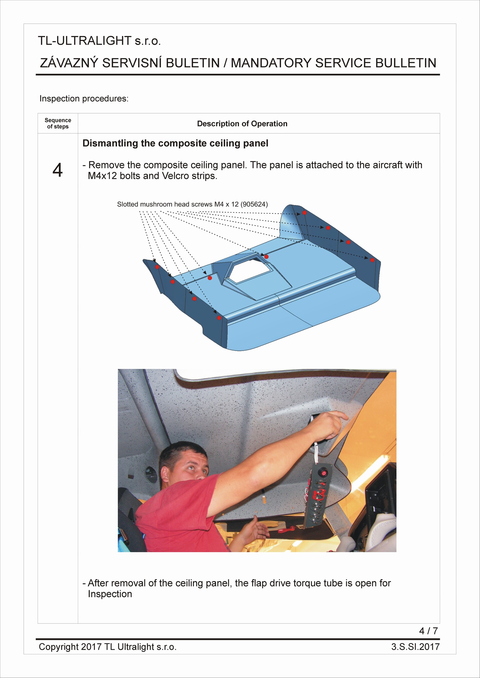
Dismantling the composite ceiling panel
- Remove the composite ceiling panel. The panel is attached to the aircraft with M4x12 bolts and Velcro strips.
- After removal of the ceiling panel, the flap drive torque tube is open for Inspection
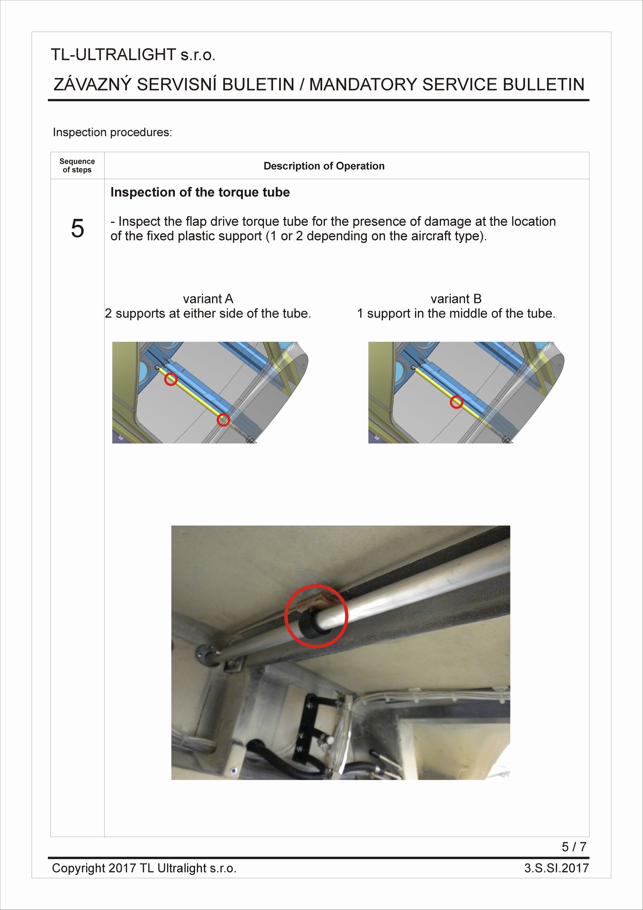
Inspection of the torque tube
- Inspect the flap drive torque tube for the presence of damage at the location of the fixed plastic support (1 or 2 depending on the aircraft type).
Variant A
2 supports at either side of the tube.
Variant B
1 support in the middle of the tube.
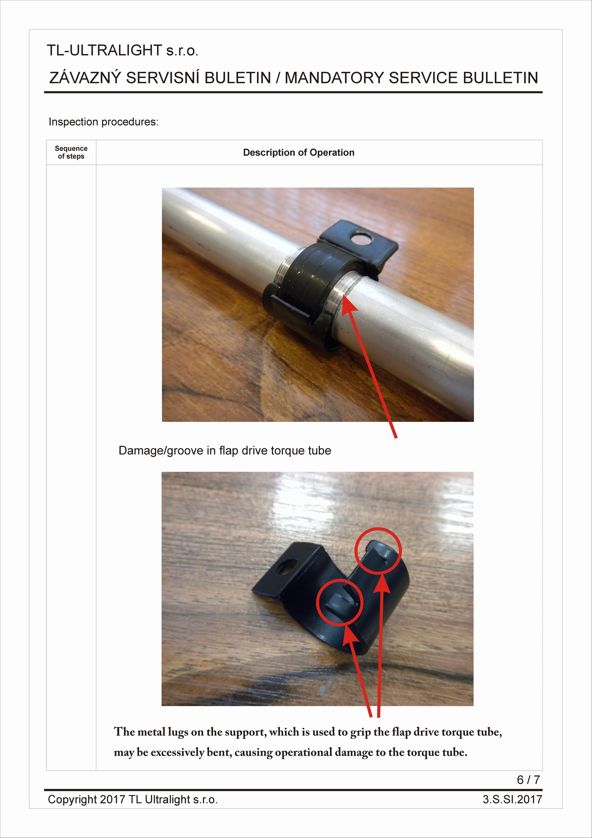
Damage/groove in flap drive torque tube
The metal lugs on the support, which is used to grip the flap drive torque tube, may be excessively bent, causing operational damage to the torque tube.
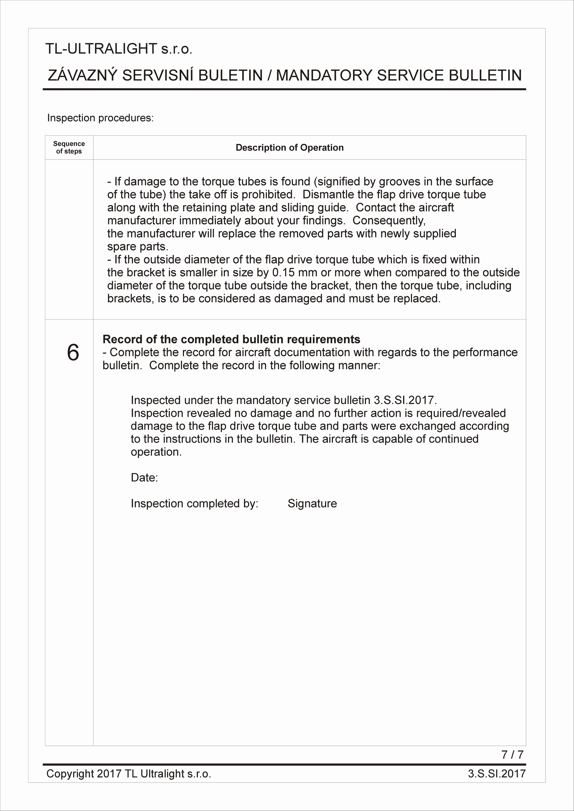
- If damage to the torque tubes is found (signified by grooves in the surface of the tube) the take off is prohibited. Dismantle the flap drive torque tube along with the retaining plate and sliding guide. Contact the aircraft manufacturer immediately about your findings. Consequently, the manufacturer will replace the removed parts with newly supplied spare parts.
If the outside diameter of the flap drive torque tube which is fixed within the bracket is smaller in size by 0.15 mm or more when compared to the outside diameter of the torque tube outside the bracket, then the torque tube, including brackets, is to be considered as damaged and must be replaced.
Record of the completed bulletin requirements
Complete the record for aircraft documentation with regards to the performance bulletin. Complete the record in the following manner:
Inspected under the mandatory service bulletin 3.S.SI.2017.
Inspection revealed no damage and no further action is required/revealed damage to the flap drive torque tube and parts were exchanged according to the instructions in the bulletin. The aircraft is capable of continued operation.
Downloads
- rev01-aj.pdf (PDF 3,3 MB)
Fotogalerie